All Activity
- Yesterday
-
Hi all, hope you are well. I was just curious.. from when to when were the Jugglers being manufactured? Usually, on a page (for example the Jester Series https://www.vari-lite.com/global/products/jester-series) it tells you when they were manufactured, this case being 2008-2017 for the ML range. However, on the Juggler page (https://www.vari-lite.com/global/products/juggler) it does not mention the manufacture date anywhere. I am aware that the Jester Series superseded the Juggler, but does anybody know this information per chance? Many thanks for any info you can supply me with.
-
Jon's departure post says this is the official contact email address to use: Conversely, the Vari-Lite website (https://www.vari-lite.com/global/support/technical-support) says to use support@zero88.com - I imagine this redirects somewhere new now...
- Last week
-
Just to be sure, people in this thread who have already emailed support (@ATC Tech and @Charlie Newman) and haven't got a reply, have you used one of the old email routes, or the functional one? I've used this address, 'zero88support@signify.com' and have got replies before.
-
Following as i have the same problem for IOS here in Australia. I have downloaded before on other iPhones and iPad but can’t download now. Not available in my region error. I have emailed support, but no response yet.
-
Unfortunately, same issue here too. I cannot seem to find any trace of the ZerOS Monitor and Remote apps on the Apple App Store, even in the ‘My Purchases’ section which is meant to show every app on your device added via the App Store. Luckily I have them downloaded already on two iPhones and two iPads and they still work. Hopefully we shall see what happens with the email to Signify. If I remember correctly, these apps were still under the Eaton Apple Developer App Store account. Not sure.
-
Hi @Tim Molyneux, the above post should definitely solve your problem (thank you @mikeb) as you are trying to load in a fixture personality file in the way of loading a fixture library file onto the desk. Using 'Assign Fixtures' -> USB as described in the manual above will work. Regarding this, I thought I'd just chip in and mention about file formats for future reference: JOS files are the file format for the Jester operating system when updating the console's OS. JSF files are showfiles for Jesters in the 12/24 and 24/48 range. JML files are showfiles for Jesters in the ML range, TL and TLextra range. I hope this is of use for the future for file format knowledge. Edit: To add, I have attempted to upload the IFT file provided above on my own JesterML console using the method in the manual via 'Assign Fixtures' and it does load in correctly.
-
A JOS file is likely to be a showfile. A fixture personality file is an IFT file so it may be they way you're trying to load the IFT file? Found this from Ed on another forum... The <Update Library> option in Super User can be used to update the fixture library on the console. If you just wish to load in a fixture file, not a whole library, please see page 49 of the Jester TL manual for information on assigning fixtures… https://www.zero88.com/storage/downloads/5ebda1d3-7348-4727-ae31-fecedf299a46/Jester-TL-and-TLXtra-Manual-3.0.pdf#page=49
-
I'm like Ben in the thread - at the limit if my abilities. Any help is massively appreciated. I had to spend the last £200 on these cheap and cheerful movers for the Drama studio (at last I have an A level lighting student!), they don't need to be brilliant but they do need to work, otherwise I'm in for an awkward conversation with the school finance office.
-
That’s weird. I see from this thread, I wrote an IFT fixture for another user using the 2.6 fixture tools and he reports it loaded and worked ok. This needs more investigation…
-
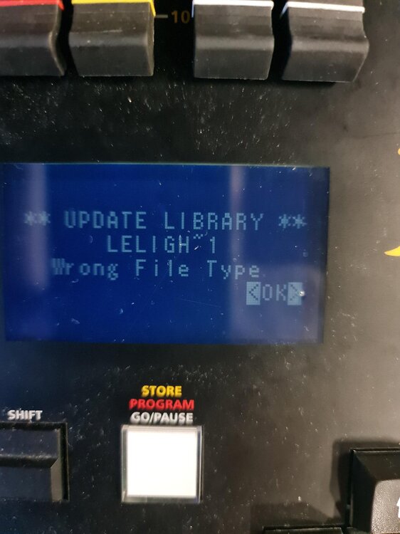
Bad news I'm sorry to say, the desk is coming up with the same error 'wrong file type'. I wonder if it should be a JOS file? Is it worth me deleting the library and starting again do you think? Thanks, Tim
-
Hi Philh, having the same issue here. I've contacted Signify but I don't have the world of confidence in getting a reply unfortunately.
-
Thanks so much for your help Mike, I'll try it later today and let you know. Tim
-
I was using the iOS version of zeros remote but after a recent change of iPad I find it is “ no longer available in your region” I use it frequently is there a solution?
-
Hi Give the attached a go and let us know how it goes LeLight LED Moving.ift
-
Hi The 17ch IFT seems empty and the 25ch IFT only shows 4 DMX channels with just a dimmer. I'll look to create a single IFT file that contains both modes
-
Thanks for the reply. I started the new thread when I noticed how old the previous one was - I'm delighted you are here. I have attached the 2 files I created using the software on this link (2.6): https://vari-lite.s3.eu-west-1.amazonaws.com/software-firmware/zero-88-fixture-tools-2.6.zip It is very possible I set one of the parameters incorrectly - I am not (by any means) a lighting expert. I have also attached the channel descriptors for the light in case you are able to spot any errors - assuming you are happy to give the time. Thanks again, Tim LeLight LED Moving 17ch.ift LeLight LED Moving 25ch.ift
.thumb.jpg.175221d69827371f56e2a05aca81c683.jpg)
-

Stopping Movers after a cue with an effect running
kgallen replied to Worcester RGSTech's topic in Solution & Solution XL
OK, I have an answer, employing "secret sauce". If the console is in global cue only mode, this means that upon recording, tracking will be Cue Only, and fixtures that are on will be snapshotted. Therefore, to capture values for fixtures that are currently off (0%), you would need to do a full snapshot. So go into the cue, stop the effect, SHIFT+RECORD > type the cue number > ENTER > Overwrite. @Worcester RGSTech I hope this finally solves your issue! -
Stopping Movers after a cue with an effect running
kgallen replied to Worcester RGSTech's topic in Solution & Solution XL
If that’s the case, how does he record No Effect in Cue Only? This needs insider knowledge of ZerOS. Where is @Edward Z88 when you need him! -
Did you use Fixture Tools 2.6 and save an ift file? It should just work… Can you elaborate more on what you did? Maybe upload your fixture file here and we can take a look. I see you started a new thread - maybe we can continue on that (but please avoid double-posting, you won’t get help any quicker…).
-
Hi, I have bought a pair of 19x15 LED Moving heads from Amazon 2Pcs 19 LED 285W Wash Zoom Moving Head, RGBW 4 in 1 Professional Focus Dye Stage Light with Light Strip and 4 Control Modes for Party KTV Concert Music Festival Christmas Wedding Celebrations : Amazon.co.uk: Musical Instruments & DJ and I have created a fixture for it using the Zero88 software but my Jester 24 ML is not recognising the file type when I attempt to update the library. Any suggestions? Thanks, Tim
-

Stopping Movers after a cue with an effect running
mikeb replied to Worcester RGSTech's topic in Solution & Solution XL
I think you're right about 'cue only' recording everything but believe the gotcha is that if intensity is 0 then it's a flag that says not to record colour/position/beamshape nor effect information. The only way over this is like @kgallen has said - Earlier
-
 Thats what I thought as well, that 'Cue Only' should record 'everything'. ZerOs does tend to baffle me. All a bit 'Fisher Price my 2nd Lighting Board' in comparison to the old Strand 500 series or ETC Eos family.
 -
Stopping Movers after a cue with an effect running
kgallen replied to Worcester RGSTech's topic in Solution & Solution XL
If you’re in cue-only mode then I thought the console records ‘everything’. In which case your ‘No Effect’ should have worked regardless. Maybe that’s not how ZerOS works! In cue-only I wonder if move on dark can ever work. Hmmm. Others more experienced with cue-only may know! -
It seems that 'Smart Tag' does only show as a button when set in Tracking Mode. - when I put the desk into 'Cue Only' the Smart Tag button disappears. This all makes some sense now. Thank you


.jpg.a927d3cbe4dfbeb836e238af9117155d.jpg)